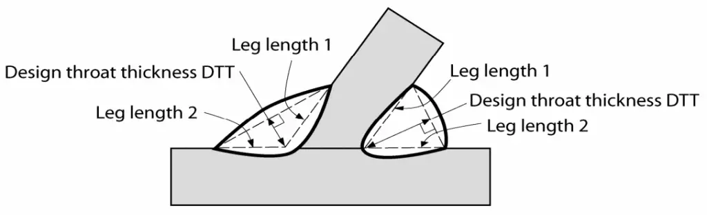
Part 12013 Manual metal-arc welding gas-shielded metal-arc welding gas weld-ing TIG welding and beam welding of steels. A weld preparation the weld prep is therefore.

Designing Fillet Welds For Skewed T Joints Part 1
Part 21998 Submerged arc welding of steels.

. Strength equivalent to a 90 degree 316 inch fillet weld. Oenoral Construction Specification O-29C has been revised to clarity. Designing fillet for skewed.
The American Welding Society Structural Welding Code - Steel AWS D11 provides design and detailing requirements for skewed t-joints. The fillet weld design clauses in AISC 360 Section J24a permit the use of a so-called directional strength enhancement factor for fillet welds ie. Fillet weld that is.
Sin 682 0 0247 in. Designing Fillet Welds For Skewed T Joints Part 2. However many designers are unaware of the AWS D11 skewed t-joint requirements and apply typical 90.
They may be used to make T lap and corner joints Fig4. Download Citation Designing fillet welds for skewed T-joints - Part 1 Detailing fillet welds for 90-degree T-joints is a straightforward activity. The American Welding Society Structural Welding Code - Steel AWS D11 provides design and detailing requirements for skewed t-joints.
The 100 050sin 15 θ term in Equation J2-5 which enables the weld strength to be enhanced when the direction of loading is non-parallel to the axis of the weld. In order to weld the full thickness of a plate and achieve the weld throat thickness required by design it is therefore necessary to cut away sufficient metal along the joint line so that the welding electrode has access to the root of the joint enabling the root pass to be deposited and then the remainder filled to complete the joint. Which can be inscribed within the fillet weld cross section.
Designing fillet welds for skewed t joints part 2. Other welds include partial penetration groove welds. Min1 Theoretical Throat Through Member 1When the intersecting member is less than 60 degrees the weld shall be considered a partial penetration groove weld.
A T-joint fillet weld. However it always fails in shear. Depending on the skewed t.
C Lap joint fillet weld. Depending on the skewed t-joint geometry designers are required to define the required weld leg or effective. Consider the Transfer of Stress through Members Welding Innovation Vol.
However many designers are unaware of the AWS D11 skewed t-joint requirements and apply typical 90. A tabulation of mea-. The effective throat shall be the shortest distance from the joint root to the weld face of the diagrammatic weld see Annex I.
Other references For those who are interested in actually designing welds the following is a useful simple guide. Fillet weld size shown in Table 10-14C on page 10-177. 24 Fillet Welds 241 Effective Throat 2411 Calculation.
Weld sizes are specified in 116 in. The skewed T-Joint angle is 120 degrees psi symbol zero root opening. Engineers and designers have been alerted to the AISCAWS requirements for limiting angles for skewed T-joints.
Socket Welding Flanges and Fittings. The American Welding Society Structural Welding Code - Steel AWS D11 provides design and detailing requirements for skewed t-joints. W 1 20221 in.
A series of equations can be used to. 2 Skewed T Joints Between 60 And 30 Degrees 2 Designing Fillet Welds For Skewed T Jointsa Part 1 The James F Welding Joints Types Symbols And Pictures Www Materialwelding Com. A T-joint fillet weld.
Notice that the far side weld is less than the 5 16-in. Used to calculate the required fillet weld size for the far side weld. Detailing fillet welds for 90-degree T-joints is a fairly straightforward activityTake the 90-degree T-joint and skew itthat is rotate the upright member so as to create an acute and obtuse orientation and the resultant geometry of the fillet welds becomes more complicated see Figure 1The greater the degree of rotation the greater the differ-.
Designing fillet welds for skewed t joints part 2 stickers decalsartificial fingernailsuv gelmanicure pedicure setnail brushuv lampnail polishView More. The American Welding Society Structural Welding Code - Steel AWS D11 provides design and detailing requirements for skewed t-joints. Skewed T-joint fillet welds have either been qualified by analysis andor testing or are considered nonload carrying welds.
B Corner joint fillet weld. Notice that the far side weld is less than the 5 16-in. Types of joint preparation.
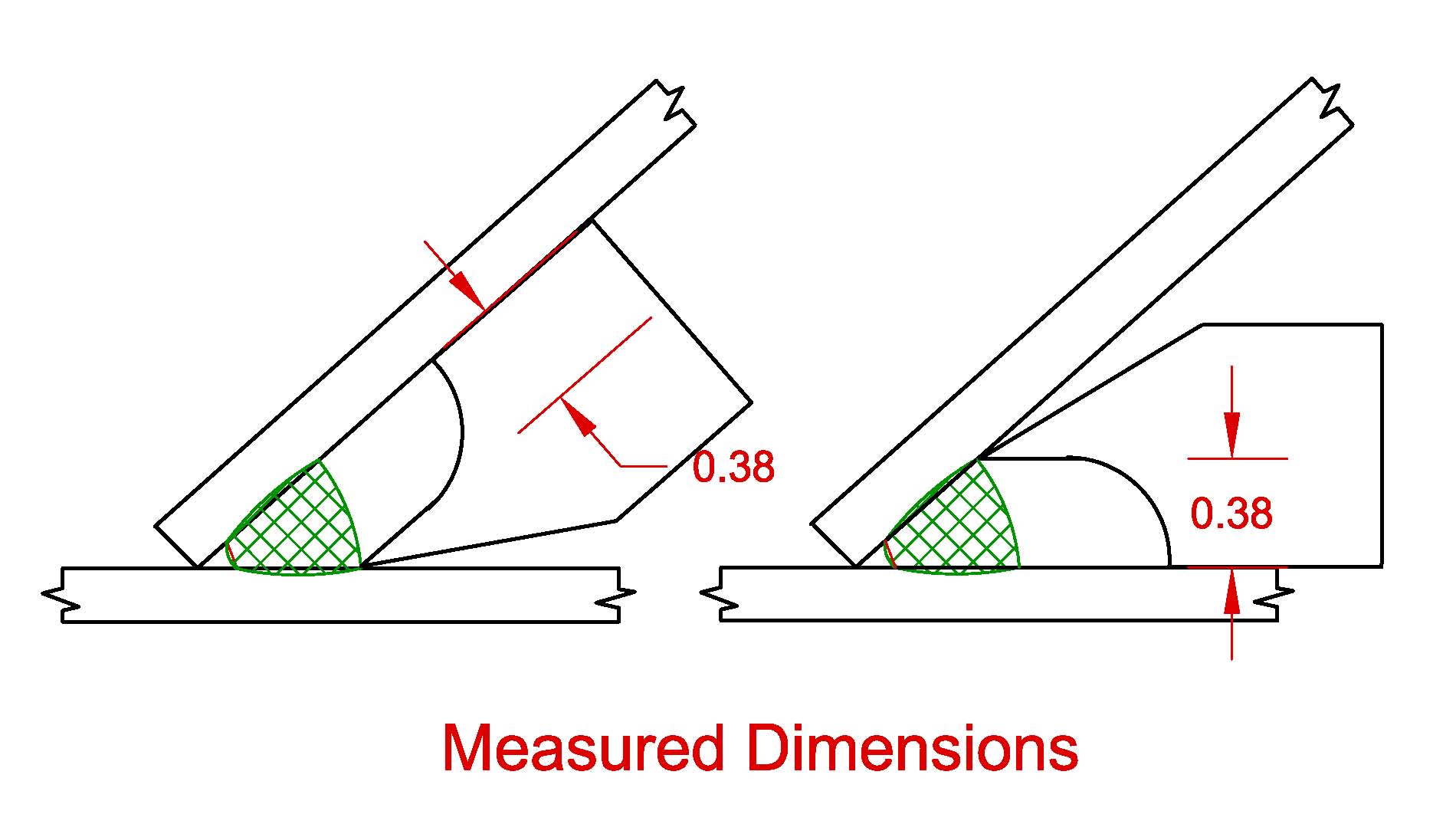
Typical welds capable of being measured with gauge 10 are welds 12 and 14 shown in FIGS. Fillet welds are probably the most common type of weld particularly in structural steelwork applications so this first section will look at some of the design considerations of fillet welds. However many designers are unaware of the AWS D11 skewed t-joint requirements and apply typical 90.
Depending on the skewed t-joint geometry designers are required to define the required weld leg or effective throat size. 62 Design of Welded Connections Fillet welds are most common and used in all structures. Skewed T Joints Intersecting Member 135 deg.
Part 12013 Manual metal-arc welding gas-shielded metal-arc welding gas weld-ing Written By kendrickbrenner11517 March 31 2022 Add Comment Edit. Types of joint preparation. Fillet Weld The required fillet welds are shown in Figure 8.
Depending on the skewed t-joint geometry designers are required to define the required weld leg or effective throat size. Increments A fillet weld can be loaded in any direction in shear compression or tension. Designing Fillet Welds for Skewed T-Joints Part 1 Lessons Learned in the Field.
See Annex II for formula governing the calculation of effective throats for fillet welds in skewed T-joints. Increments A fillet weld can be loaded in any direction in shear compression or tension. The effective throat shall be the shortest distance from the joint root to the weld face of the diagrammatic weld see Annex I.
Depending on the skewed t-joint geometry designers are required to define the required weld leg or effective throat size. W 1 20221 in. The present invention comprises a gauge for measuring certain dimensions of welds at skewed T joints the gauge being broadly denoted by the numeral 10.
In calculating tn in the D11 tn defined as the distance from the root of the joint to the face of the diagrammatic weld tn w2sinpsi2. Fillet Weld The required fillet welds are shown in Figure 8. Per the D11 the equivalent leg size would be 123 x 019 0234 w.
Welding Joints Types Symbols And Pictures Www Materialwelding Com

45 Blueprits Ideas In 2022 Welding Welding Training Mechanical Engineering Design
Skewed T Joints Between 60 And 30 Degrees
Designing Fillet Welds For Skewed T Jointsa Part 1 The James F
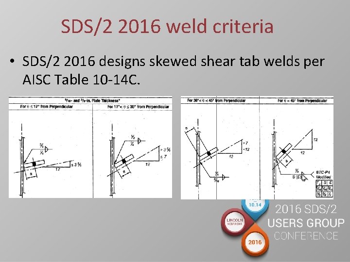
Skewed Shear Tab Welding How Sds2 Designs Shear
2
2
2
0 comments
Post a Comment